Help on interfacing PL GPIO Devices to Custom HDL Workers

Hi community!

I’m having some problems using GPI/GPO HDL workers. When I run the OAS on my target platform (in this case the ZCU104), I keep getting the following error:


OCPI( 8:419.0916): Starting proxy workers that are not slaves.
OCPI( 8:419.0916): Starting proxy workers that are also slaves, but not sources.
OCPI( 8:419.0916): Starting proxy workers that are also slaves and are sources.
OCPI( 8:419.0916): Starting workers that are not proxies and not sources.
OCPI( 8:419.0916): Error Exception: Port “in” of instance ‘a/GPIO_Test’ worker “GPIO_Test” is not connected
OCPI( 8:419.0916): HDL Control Op Avoided worker GPIO_Test:a/GPIO_Test(2) op release(3)
OCPI( 8:419.0917): Worker “release” control operation succeeded, now in state “EXISTS”: worker “GPIO_Test” in container PL:0 from artifact worker GPIO_Testhdl/a/GPIO_Test
Exiting for exception: Port “in” of instance ‘a/GPIO_Test’ worker “GPIO_Test” is not connected

Where “GPIO_Test” is an HDL worker that interfaces to gpi.vhd and gpo.vhd HDL devices.

In my gpi.xml file (the OWD), I’ve declared a single signal input:

And the output of this device worker is a stream interface of 32 bits.
As far as I have read, “gpi_pin” is an internal signal that points to the GPIO pin of the FPGA.

Thus, my HDL container looks like this:

<HdlContainer Config="base" Platform="zcu104" constraints="zcu104.xdc">
    <Connection external='in_to_asm_button_path' Port='out' Device='gpi'/>
    <Connection external='out_from_asm_led_path' Port='in' Device='gpo'/>
</HdlContainer>

Where “in_to_asm_button_path” means “the button path into the assembly”, and “out_from_asm_led_path” means “the LED path from the assembly”

And my HDL assembly looks like this:

<HdlAssembly>
    <Instance Worker="GPIO_Test"/>
 
    <!-- OCPI HDL to User HDL -->
    <Connection Name="in_to_asm_button_path" External="consumer">
        <Port Instance="GPIO_Test" Name="in"/>
    </Connection>
 
    <Connection Name="out_from_asm_led_path" External="producer">
        <Port Instance="GPIO_Test" Name="out"/>
    </Connection>
 
</HdlAssembly>

Finally, my component spec for GPI is:

<ComponentSpec>
    <Port Name="out" Protocol="gpio_protocol" Producer="true"/>
</ComponentSpec>

And my component spec for GPIO_Test (the HDL worker) is:

<ComponentSpec>
    <Port Name="in" Producer="false" Protocol="gpio_protocol"/>
    <Port Name="out" Producer="true" Protocol="gpio_protocol"/>
</ComponentSpec>

So basically, I can’t see where else I need to/can interface the output stream interface from GPI to GPIO_Test.

Does anyone have any example code that connects a push button to an HDL worker via the HDL assembly + container? I can’t find any examples online or in the builds, and I feel like I’m going around in circles :confused:

I have suspicion the problem lies in the HDL assembly when connecting HDL devices to HDL workers, but an example would be very useful to help see how it’s wrong.

Thanks in advance!
@RJ076 thanks for reaching out. The more discussions we have like this the more knowledge can be shared.

It looks like you are using the base HDL configuration for zcu104 in your container. I think the part you are missing is how the device workers are instantiated and FPGA pins are assigned. Without instantiating the device workers the rest will be left unconnected.

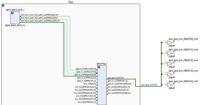
When debugging assemblies it’s helpful to open it up the design checkpoints and confirm at a high level using the schematic viewer that workers are connected as expected and have not been optimized out. These can be found in the assembly directory under gen/container-xxx/target-xxx/ with the .dcp extension.

Below is an example of showing connection from example gpio_pass hdl assembly to output pins on the FPGA:

From what I can tell from what you have shared above, the gpi and gpo device workers have not been instantiated.

Where the magic happens when it comes to device workers is in the platform worker. Reminder, device workers are special workers that allow you to interface to external pins on the FPGA.

The platform that I had on hand and built was zed so I made modifications to add these device workers. In a couple of days, if I have the time, I could provide an example for the zcu104.

I have rough cut of the changes I made to provide an example. Additionally, an OpenCPI project named gpio-test can be found on this branch: Files · exmaple-gpio-device-worker · OpenCPI / OpenCPI · GitLab

Platform Worker

Essentially, the platform worker xml zed.xml found in projects/platform/hdl/platform/zed directory contains a list of the devices that could be used on the platform. The push buttons and LEDs on the board are part of the platform and should be described in the platform worker xml. What is found on the repository at the moment does not instantiate gpi or gpo device workers. So these need to be added.

A hdl platform can have multiple platform configs, these configs specify which devices will be enabled when building the platform worker. These must be a combination that is described in the platform worker xml. There’s a whole other level with cards/slots that I’m ignoring at the moment. In order to build different variants of the platform configs the configs need to be added to the platform worker xml.

In the example branch I added: cfg_gpi, cfg_gpo, cfg_gpio configurations.

Under projects/gpio-test/hdl/assemblies you’ll find two assemblies. These are currently a work in progress. I did test gpi version of the empty assembly. Where I validated that I can read the mask_data property using ocpihdl on the device and I could see the bits change when pushing the push buttons.

I’m in the process of creating a pass through worker similar to your GPIO-test to facilitate passing data from gpi → asm_in → passthru → asm_out → gpo . As described in your initial post.

Now that the platform worker has hdl configurations that instantiate the device workers these can used to build assemblies with them.

Assembly

Starting with the empty assembly. To use of the correct hdl configuration, inside the container xml use the attribute config. The FPGA assignment to gpi_pins occurs with names of signal gpi_pins and mapped to the pin via the constraint file; defined by attribute constraints in the same xml. Following the same the same example assembly it looks like this.

To Be Continued

Long story short. I’m in the processes of creating said example. Let me know if I interpreted your original intent correctly so far.

I can switch to zcu104 so that you can also run what I am running.

In the meantime if it’s helpful you can investigate my current branch. I will keep you updated on my progress creating this example.

Hi @aolivarez ,

That’s already super helpful, thanks for putting in such a lot of work to explain the process in such detail!

I think I understand where I was going wrong, so I’ll have a play with configurations in the assembly, and let you know how I do. Unfortunately I don’t have the ZCU104 with me today, but I’ll do a build tomorrow and see what builds (or rather what doesn’t build haha), so thanks a million for all you’ve done so far!