ANTSDR e310 OSP

This documents the journey from getting a Zynq7020+AD936x based device up and running with OpenCPI by creating and OpenCPI System Support Project (OSP) for it.

This quick run through uses the following versions:
OS: Ubuntu 24.04 or Ubuntu 22.04
OpenCPI: v2.4.8 or v2.4.9
Xilinx Vivado: 2024.1
Xilinx PetaLinux: 2024.1

Target Hardware - ANTSDR E310 - (HAM Geek Clone)
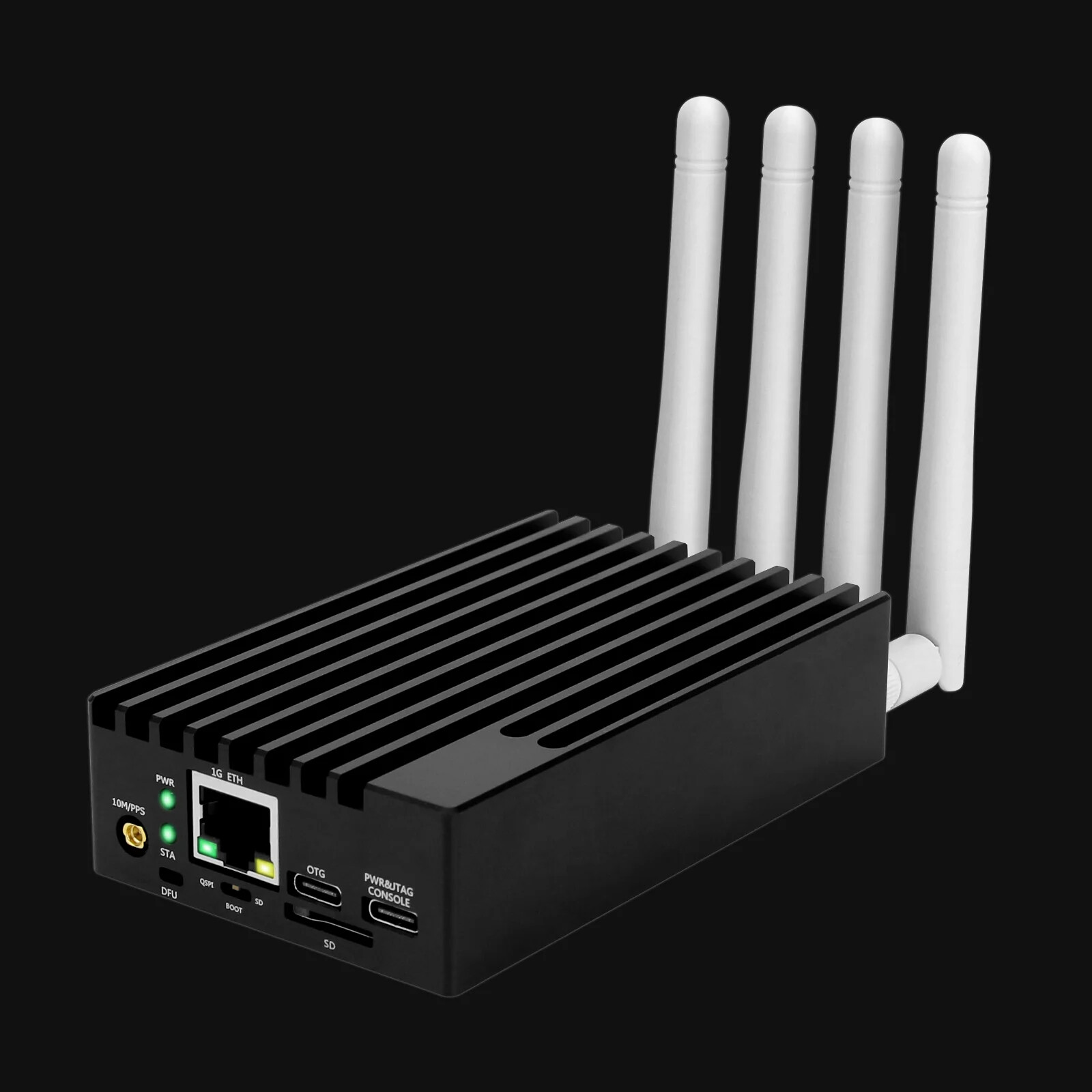
Specifications:

  • Brand: HAMGEEK
  • Model: E310
  • RFIC: AD9361 for ADI. Frequency 70M~6G (A9361). Up to 56M instantaneous bandwidth (AD9361)
  • Number of channels: 2T2R MIMO
  • Baseband processing: ZYNQ7020, dual core for ARM, Cortex-A9 1G Byte DDR3 RAM. 256Mbit QSPI
  • Baseband processor: ZYNQ XC7Z020
  • Interfaces: one Giga ETH, one USB 2.0, Type C USB-JTAG and USB-UART, and GPIO expansion
  • Synchronization: External 10M, PPS inputs
  • Clock: VCTCXO with an initial accuracy of 0.5ppm. Dynamically adjusted clock via digital PLL. The accuracy can be better than +/-5ppb
  • API: For ADI IO (pre-installed), C/C++, and Python
  • Dimensions: Board: 100mm x 60mm/3.9" x 2.4"; case: 107.5mm x 64.5mm x 23mm / 4.2" x 2.5" x 0.9"
  • Power supply: USB TYPE-C powered
  • Transmit power: 3dBm (depends on frequency)
  • ADC: 12bit 61.44MS/s
  • DAC: 12bit 61.44MS/s
  • Noise figure: < 8db
  • Power consumption: 2~6W
  • Transmit IQ bandwidth: 10MSPS
  • Host interface: 1G ETH
  • GPS: None
  • External synchronized clock: 10M/PPS
  • Features: Hobbyist development, DIY, and open source code

Schematic

One of the crucial pieces of information you will need to create the OSP is the device’s schematic: Which can be found here.

Create HDF Files

A vivado hardware description file is a container that contains all the necessary information needed to build the correct boot artifacts.

  1. Open Vivado 2024.1
  2. Create Vivado Project
  3. Select Correct Part Number (xc7z020clg400-2)
  4. Create Block Design (design_1)
  5. Add ZYNQ7 Processing System Block
  6. Run Block Automation

From this point on follow this detailed guide on what needs to be done in the block design: Zynq HDF Creation Guide

Essentially you’ll take the schematic (Banks 50x) for the board configure the Zynq Processing System and do the following:

  • Ensure MIO pins match locations on the board
  • Add external ports to the 100MHz clock into the FPGA fabric to feed the control plane and data plane
  • Add external ports to access AXI control plane and data plane and make sure they are configured properly.

You should end of with a BD that looks like this:
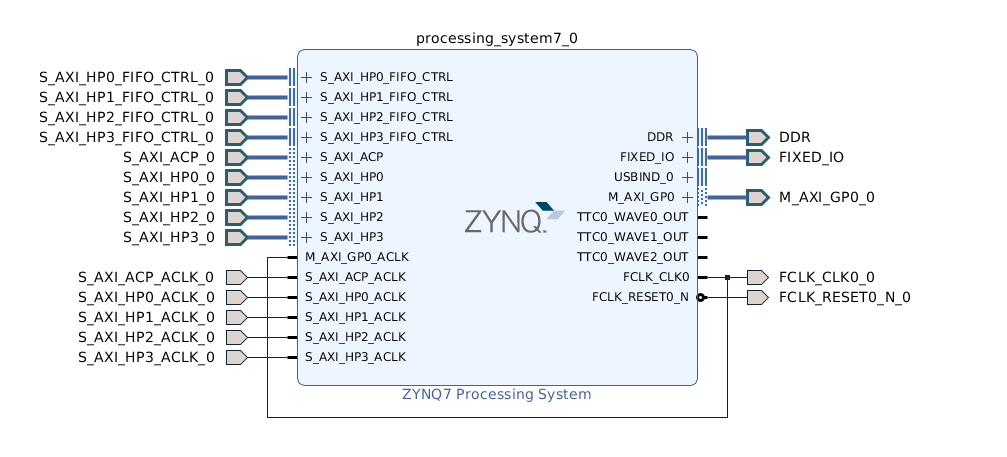
At this stage you are ready to export HDF File for PetaLinux.

File → Export → Hardware

Configure Petalinux

These are the minimum settings you need for the xilinx24_1_aarch32 platform to be compatible with this device.

  1. Source petalinux settings
  2. Create petalinux project using template
    petalinux-create --type project --template zynq --name plx-ant-e310-minimal
  3. cd into plx-ant-e310-minimal
  4. Point to the HDF file created in the previous step
    petalinux-config --get-hw-description= point it to the xsa

A window will pop up make the following modification:

DTG Settings → Kernel Bootargs → Add extra boot args
Add clk_ignore_unused

exit & save

The bootarg added above ensures that the 100MHz is enabled.

  1. Modify the rootfs
    petalinux-config -c rootfs

Image Features → debug tweaks
debug-tweaks
empty-root-password
serial-autologin-root

  1. Build the petalinux project
    petalinux-build
  2. Generate boot artifacts
    petalinux-package --boot --uboot --fsbl

Under images directory you should now have image.ub, boot.scr, BOOT.BIN
These make up the files in the releases tar that boots the device into Linux.

  1. Create release .xz

Name directory 2024.1-<platform_name>-release
tar -cJf 2024.1-<platform_name>-release.xz 2024.1-<platform_name>-release

Release Artifact for a310: Prebuilt Release

Create initial OSP

First thing we want to do is be able to get hardware acceleration working. This is accomplished by building and running the testbias.xml assembly and application.

  1. Create OSP Project ocpidev create project
  2. Create directories hdl/platforms/a310
  3. Modeled OSP off existing Zynq platforms. This is mostly a copy & paste exercise with some name changes.

* note: Zynq Ultrascale based platforms have additional kernel & rootfs configuration that differ from this platform. I plan on creating a similar run through in the future.

Add AD936x Support

First question to answer is whether the platform supports the CMOS or LVDS interface on the AD936x?
Similar exercise as hardware accelerate, use the E310/PlutoSDR as CMOS the reference or zed+fmcomms for LVDS. After comparing the pinouts it was evident that this device matched exactly libresdr platform.

The DRC from examples project works, a new one will be needed to correctly switch the RF switch > 3Ghz but I was able to verify TX capability.

The a310 OSP still needs some polishing but it is located here: Aaron Olivarez / ANTSDR · GitLab
Hi Aaron, thanks for putting this together with the e310 ettus now hard to get hold of.
I’ve got the test bias working following your code. I’ve attempted to then get a receive and file write going but hitting difficulty.

“Exiting for exception: HDL Control Op Failed: worker data_src_qadc_csts-1:p/data_src_qadc_csts0(6) op start(1) timed out performing control operation (no OCP response on the WCI) (0xc0de4203)”

Am I right in interpreting your libresdr comment above as meaning it is CMOS?

If that is right do I need to modify things such as lvds_p to false in say a310.xml and cfg_*(Aaron Olivarez / ANTSDR · GitLab)? Possibly also change the XDC to be CMOS 2.5? Then also data_clk_delay and fb_clk_delay to match e310?

I’ve tried everything up to changing the clk_delay but no luck so far so wondering if it’s the wrong direction. Is there anything obvious that you can see I’m doing wrong?

Thanks

Hi Richard,

I’m using LVDS interface on the ad9363 so lvds_p should be true. Where did you source your device? The unit I have is not a true “ANTSDR” , it is a clone. I’ve ran the receive app successfully on it.

That message indicates trouble with the data interface.

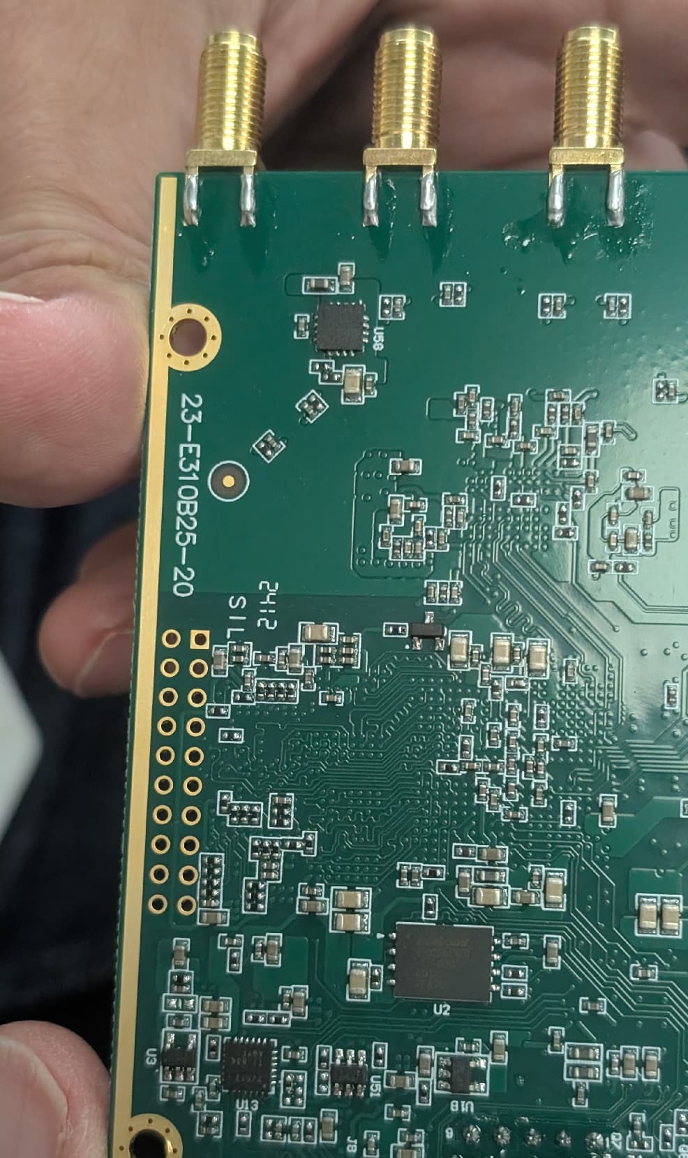
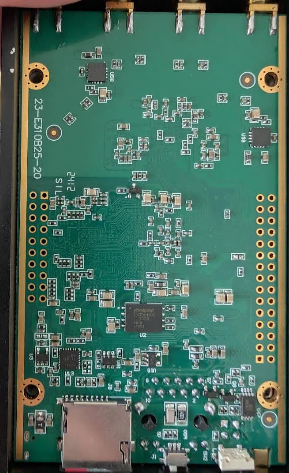
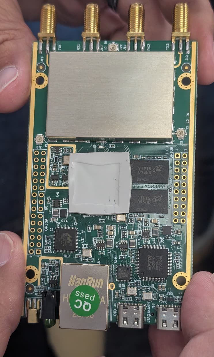
This is what the internal PCBs of the unit I tested this OSP against. Does it match yours?


Hi Aaron,

I’ve got the hamgeek ANTSDR E310 that has the AD9361 from the link in the first post . Am I right in thinking you’ve got their AD9363 version? Does that chip make much difference though, naively I thought it was just a small upgrade with no real pinout difference.

The back of my PCB looks very similar to yours though.

I’ll go back a few steps and retry the receive app in case I missed something at that point.

You are right I got the AD9363 version.

The AD9361 is pin compatible and I’ve used the ad9361 device workers interchangeably so it should work for either one. The difference is that it has a better tuning performance across 70MHz - 6Ghz , the ad9363 is narrower.

Both boards look very similar so it should be the same variant.

How are you running the applications? Are you using ocpiremote? standalone? I’ve only done ocpiremote mode with the drc built for ubuntu24_04 my development host. If running ocpiremote the DRC needs to run on the development host. I’ve ran into issues with the drc running on the device but executing the app from the host.

A couple of other things you can try:

  • Rebuilding the assembly. Maybe the constraints are not tight enough and build varies.
  • Attempt to bring up the signal_analyzer_app. Another app that I’ve tested with this device.

Thanks Aaron, I’ll try the signal_analyzer_app.

I’ve been running standalone, using nfs mount to get the artifacts and bits onto the unit and then just ssh’ing in and doing an ocpirun my.xml.

What type of issues did you have with the drc running on the device?

It should work in standalone configuration. ocpiremote mode is just the default mode I run apps in, so that doesn’t sound like that’s the issue you are running into.

Correction on a statement I made earlier, the one I have is the ad9361. I got confused with other devices from ham geek that sometimes come with an ad9363 or ad9361, but as mentioned before that shouldn’t make a difference.

Hi Aaron,

Just thought let you know got it going. In the end just changing DRC application xml property to the following resolved (had 1 before):

<Property Name='start' Value='0'/>

I noticed in a310.xml it had some commented out code around the vctcxo: a310.xml

Is that something you were working on separately for freq control - on E310 ettus I don’t think I ever saw something in opencpi doing that?

1 Like

Glad to hear you got it working. I’ll make that correction in the repo.

So I have another OSP for a similar SDR called libresdr it has a similar circuit that the ettus e310 had to discipline the 40MHz clock going into the ad936x . The frequency control commented out that you discovered was for the libresdr the a310 also has a similar circuit.

You can find it here: hdl/devices/vctcxo_lock.hdl · ref-clk-support-2 · Aaron Olivarez / LibreSDR · GitLab

Its not fully complete or tested yet.

Thanks for sharing the vctcxo_lock library. I was going to have a look at this in the near future. From a quick look at the schematic it seems as though the main differences will be:

  • the LTC2630CSC6 instead of the dac*311_spi.vhd
  • the clocking may be different as the 40m on sheet 13 of schematic I don’t think is the same.
  • just use ref_1pps (that was fairly easy to wire up)
  • possibly some changes in the constraints around:
    set_property -dict {PACKAGE_PIN H18 IOSTANDARD LVCMOS33} [get_ports dac_cs_n]
    set_property -dict {PACKAGE_PIN F19 IOSTANDARD LVCMOS33} [get_ports dac_sclk]
    set_property -dict {PACKAGE_PIN F20 IOSTANDARD LVCMOS33} [get_ports dac_din]
    set_property -dict {PACKAGE_PIN H16 IOSTANDARD LVCMOS33} [get_ports vctcxo_40mhz]`

First time I will have attempted anything like this, does that list look roughly right to you or are there any other big gotcha’s that would jump out at you?

Haven’t taken a deep dive but that seems roughly right.

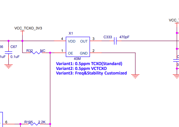
Do you think that is actually a VCTCXO on the board? I know the sales literature says it is.

I’ve set the voltage to a couple of different things now via: ocpihdl -d PL:0 set vctcxo_lock center_dac 3995. I can see the voltage changing with a scope on bottom lhs pin to the 40 MHz chip (chip at X1 on the board). So I think the opencpi worker is doing it’s job. However, using a signal generator to put in a constant tone the receive peak stays stubbornly at the same frequency.

Some forums imply it doesn’t always ship with a VCTCXO and instead a TCXO - do you recognise what the chip is on your board? The only writing I can make out is MT205 and 40 something. Google doesn’t seem to find anything VCTCXO related for MT 205.

(This could or course be me doing something silly at my end)

I was afraid of that, according to the schematic it says the default is the non-voltage controlled crystal oscillator.

Screenshot 2026-07-16 010112

I’m not near my board at the moment. You may have to replace it with an voltage-controlled oscillator. You would think since the support circuity was populated that it would also be populated with a controllable oscillator.